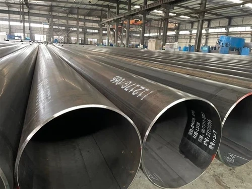
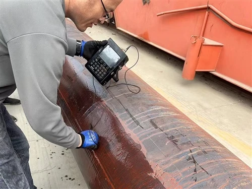
Cracking remains one of the most serious defects encountered in welded pipe production, and it is also one of the least forgiving - unlike a dimensional deviation or a surface blemish, a crack in the weld seam is a structural defect that can propagate under service load and lead to outright failure. Cracks in welded pipe are generally classified by their orientation relative to the weld line into two categories: longitudinal cracks, which run parallel to the weld seam, and transverse cracks, which run across it. This article focuses specifically on transverse cracking - why it forms, and what a producer needs to control to prevent it, with particular attention to spiral (SSAW) welded pipe, where the geometry of the helical seam adds its own considerations to the general welding metallurgy involved.
Where Transverse Cracks Actually Come From
Transverse cracks in welded pipe most commonly form during the solidification and crystallization of the weld metal itself, not afterward. As the molten weld pool cools, it solidifies progressively from the outer edges of the pool inward toward the centerline, with grains growing in the direction of heat flow. This solidification is accompanied by volumetric shrinkage - the metal simply occupies less space as it transitions from liquid to solid and continues to contract as it cools further toward room temperature.
That shrinkage generates tensile stress along the weld, and because the surrounding base metal and the already-solidified weld metal resist the contraction, the developing stress concentrates most heavily at the centerline of the weld, where the last liquid metal solidifies and where grain boundaries from either side of the pool meet nearly head-on. If that centerline region cannot accommodate the tensile stress - because the grain structure is unfavorable, because harmful trace elements have weakened the grain boundaries, or because the stress itself is higher than it needs to be due to poor process control - a crack opens perpendicular to the weld direction. That perpendicular orientation is precisely what makes it a transverse crack rather than a longitudinal one.
The diagram below illustrates this mechanism: the solidification front trailing the welding torch, the shrinkage stress pulling across the weld line as the pool cools, and the resulting crack opening at the centerline where that stress concentrates.

The Metallurgical Wildcard: Copper Contamination
Solidification shrinkage stress is a baseline condition of every weld - it cannot be eliminated entirely, only managed. But a second factor turns ordinary shrinkage stress into an actual crack far more readily: the presence of low-melting-point impurities in the weld metal, and in spiral-welded pipe production, copper is the most common offender.
Copper enters the weld pool from an unexpected source: the thin copper coating applied to welding wire to prevent surface rust during storage and to improve electrical contact and feeding through the welding equipment. As the wire feeds through the contact tip at high speed, friction gradually wears the tip's bore, and fine copper particles - both from the wire coating and, in worn tips, from the copper contact tip itself - flake off and are carried into the flux and the arc, ultimately reaching the molten weld pool.
Copper melts at a far lower temperature than steel. As the weld pool solidifies, any copper present does not solidify with the bulk steel matrix - it remains liquid longer and segregates to the grain boundaries, where it wets and weakens them. This is a form of liquid-metal embrittlement: the grain boundary, already under tensile stress from normal solidification shrinkage, now has far less resistance to that stress because copper has compromised its cohesion. The result is that transverse cracks appear at copper-contaminated boundaries at stress levels that an uncontaminated weld would tolerate without issue.

Prevention: What Actually Reduces Transverse Cracking
Preventing transverse cracking is not a matter of any single fix - it requires controlling both the underlying shrinkage stress and the metallurgical contamination that makes the weld vulnerable to it. In practice, this comes down to five areas of process control.
1. Welding Consumable Selection
The starting point is choosing welding wire and flux with a chemistry suited to the base material and free of excessive harmful trace elements. Selecting consumables carefully reduces the baseline level of impurities entering the weld pool in the first place, which lowers the probability of transverse cracking regardless of what else happens downstream in the process. This is a decision made before welding even begins, and it sets the ceiling on how clean the weld metal can possibly be - no amount of downstream process control can fully compensate for a poor consumable choice.
2. Bevel Design and Penetration Control
The groove or bevel geometry at the weld joint directly affects how much weld metal is deposited and how the solidification pattern develops. The general principle here is to reduce the internal weld bevel where possible, without sacrificing the penetration depth the joint actually needs. A smaller internal bevel, combined with adequate penetration, results in a smaller weld pool volume and a shorter solidification path, both of which reduce the magnitude of the shrinkage stress that develops as the weld cools. Getting this balance right requires close coordination between the bevel design and the welding parameters (current, voltage, travel speed) actually used on the line, since a bevel design cannot be evaluated in isolation from the process it's paired with.
3. Precision Forming and Roll Alignment
In spiral-welded pipe specifically, the accuracy of the roll-forming process that shapes the flat strip into the helical pipe body has a direct bearing on the residual stress present at the weld joint before welding even begins. If the strip edges are not brought into precise alignment - consistent gap, consistent edge height, consistent curvature matching the intended pipe diameter - the weld has to accommodate a geometric mismatch in addition to the normal solidification shrinkage. That added residual stress lowers the margin available before a transverse crack initiates. Precise forming, sometimes referred to as "shape tuning" on the production floor, reduces this residual stress at the source rather than trying to compensate for it later in the welding parameters.
4. Weld Form Factor Control
The weld form factor - the ratio of the weld bead's surface width to its penetration depth - has a direct and well-documented relationship with cracking susceptibility. A narrow, deep weld pool solidifies with grains growing steeply inward from both sides and meeting nearly head-on at the centerline, concentrating shrinkage stress along a narrow band. A wider, shallower weld pool allows grains to grow toward the center at a shallower angle, distributing the same overall shrinkage stress across a broader region rather than concentrating it.
As a practical target, the weld form factor is generally kept above 1 (bead width greater than penetration depth) specifically to avoid this stress concentration. This is controlled primarily through welding current, voltage, and travel speed settings, and it should be verified as part of routine process qualification rather than assumed from nominal parameter settings alone, since electrode wear, flux condition, and even ambient temperature can shift the actual bead geometry produced on a given day.
5. Contact Tip and Copper Contamination Control
Because copper contamination is such a disproportionately damaging factor relative to the small quantities actually involved, it deserves dedicated process controls rather than being treated as a side effect of general consumable quality. This includes scheduled inspection and replacement of contact tips before bore wear becomes significant, monitoring wire feed for visible flaking or coating degradation, and in some cases specifying wire with a lighter or alternative surface treatment where copper pickup has been a recurring issue. Because this contamination pathway is largely invisible in the finished weld until a crack actually appears, it is one of the areas where preventive maintenance discipline matters more than reactive troubleshooting.
Buying Guide: Evaluating a Welded Pipe Supplier's Crack-Prevention Practices
For a buyer sourcing SSAW or other welded pipe, transverse cracking is largely invisible in a standard mill certificate unless it has already progressed to a detectable defect caught by non-destructive testing - by which point a length has already been rejected or repaired, adding cost and schedule risk to the order. The more reliable approach is to evaluate whether a supplier's process controls make transverse cracking unlikely in the first place. The following points are worth confirming before placing an order, particularly for larger or higher-specification projects:
- Ask how weld form factor is monitored, not just set. A supplier who can describe how bead width-to-depth ratio is actually measured and verified during production - rather than simply citing a target parameter sheet - is demonstrating real process control rather than a paper specification.
- Ask about contact tip replacement intervals and wire handling practices. A supplier with a defined preventive-maintenance schedule for contact tips, and controlled storage/handling of welding wire to avoid coating damage, is addressing the copper contamination pathway proactively rather than only reacting to defects after they occur.
- Confirm what forming/alignment tolerances are held before welding, especially for spiral-welded pipe, since strip edge alignment prior to the weld pass has a direct bearing on residual stress at the joint.
- Request the actual non-destructive testing coverage applied to the weld seam - full-length testing catches issues a sampled inspection regime can miss, and this matters more for crack-type defects than for most other quality characteristics, since a crack that escapes detection can propagate under service load long after the pipe has left the mill.
- Ask whether welding parameters are qualified per production run or assumed static. Because bead geometry and weld quality can shift with electrode wear, flux condition, and other variables over time, a supplier who requalifies parameters periodically - rather than treating an initial procedure qualification as permanent - offers more consistent crack resistance across an entire order, not just the first few lengths produced.
- Where the project specification allows it, ask for production data or examples from prior orders of similar diameter and wall thickness, since crack susceptibility is influenced by pipe geometry as well as process parameters, and a supplier's track record on comparable sizes is a more direct indicator than general claims about quality systems.
Transverse cracking is ultimately a controllable defect, not an inherent risk of the welding process - but controlling it requires attention to details that don't show up on a standard specification sheet: bead geometry, contact tip condition, and forming precision, all working together with sound consumable selection. Buyers who ask about these specifics at the qualification stage, rather than relying solely on chemistry and mechanical test results, are in a much stronger position to avoid the schedule and cost impact of a crack-related rejection later in the project.