

Why Does Surface Defect Detection Matter for Square and Rectangular Tube?
Square hollow section (SHS) and rectangular hollow section (RHS) go through forming, welding, and heat treatment before they reach a finished tube - and any of those steps can introduce a defect: a rolled-in lap, a seam-weld flaw, a surface crack from cold work, or a subsurface inclusion carried over from the coil. Left undetected, these defects can propagate under load, cause premature failure at a welded joint, or trigger rejection during structural inspection long after the tube has been fabricated into a finished structure.
There is no single detection method that covers every defect type, every tube geometry, and every production speed requirement at once. Choosing the right method - or the right combination of methods - depends on where the defect is likely to be, how the tube is magnetized (or not), how fast the inspection needs to run, and what surface condition the tube is in. This article walks through the five detection methods most commonly used on square and rectangular steel tube, what each one is actually measuring, and how to decide which one fits your inspection requirement.
How Does Eddy Current Testing Detect Defects on the Tube Surface?
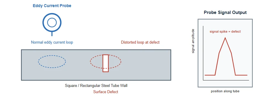
Eddy current testing (ECT) works by passing an alternating current through a coil held near the tube surface. That coil induces circulating "eddy" currents inside the metal through electromagnetic induction. When the induced current flows through a defect-free region, it forms a predictable, uniform loop. When it encounters a surface or near-surface defect - a crack, a lap, a thinned wall section - the eddy current loop distorts, and that distortion shows up as a measurable change in the coil's electrical signal.
Eddy current testing is not a single fixed technique - it covers several implementation types, each suited to different inspection needs:
- Conventional (standard) eddy current testing - the baseline method, using a single-frequency coil for general surface and near-surface defect detection
- Remote field eddy current testing (RFEC) - uses a transmitter and receiver coil separated along the tube, allowing detection through both the inner and outer wall in one pass, useful where access is limited to one side of the tube
- Multi-frequency eddy current testing - runs several frequencies simultaneously, letting the inspector separate signals from different defect depths or suppress interference from surface conditions
- Pulsed eddy current testing - uses a broadband pulse rather than a continuous wave, which can extract more depth information from a single measurement
- The strengths of eddy current testing are what make it a common first-line method on production lines: detection accuracy and sensitivity are both high, inspection speed is fast enough to run in-line during tube production, and it can pick up both surface and subsurface (near-surface) defects. It also tolerates surface contamination reasonably well - oil film or light surface residue on the tube generally does not disrupt the signal, which matters on a production floor where tubes come straight off a forming and welding line.
The trade-off is specificity. Eddy current testing is sensitive to any change in the electromagnetic response of the material, which means it can flag geometric features, minor surface roughness, or material property variation as if they were defects - raising the false-detection rate compared to methods that produce a more direct physical indication. It also offers limited flexibility in adjusting detection resolution, so an eddy current setup tuned for one defect size and depth range may not be the optimal setting for a different defect profile without reconfiguring the probe or frequency.
How Does Ultrasonic Testing Locate Defects Inside the Tube Wall?
Ultrasonic testing (UT) uses the way sound waves travel through solid metal. A transducer sends a high-frequency ultrasonic pulse into the tube wall. As long as the material is continuous, the wave travels through predictably; when it reaches an internal defect - a void, an inclusion, a lack-of-fusion in the weld seam - some of that energy reflects back toward the transducer. By measuring the time delay and amplitude of the reflected signal, the inspection equipment can calculate both the location and the approximate size of the defect within the wall thickness, not just its presence.
Ultrasonic testing's core advantage is precision: among the five methods here, it is generally the most accurate for pinpointing exactly where within the tube wall a defect sits and roughly how large it is. This makes it a standard method for verifying weld-seam integrity on both tube products and forged components, where knowing the depth of a flaw - not just its existence - determines whether the part is acceptable.
The method does have real practical constraints on square and rectangular tube. It is not well suited to complex or irregular geometry - the flat faces of an SHS/RHS work reasonably well, but corners and transition zones can distort the sound path and complicate interpretation. The tube surface needs a certain level of smoothness for the coupling to work correctly, since ultrasonic testing requires a coupling agent - typically a gel or oil-based medium - applied between the probe and the tube surface to eliminate the air gap and keep the signal transmission stable. Rough, scaled, or heavily coated surfaces need to be prepared before ultrasonic testing will give a reliable reading.
How Does Magnetic Particle Testing Reveal Surface and Near-Surface Defects?
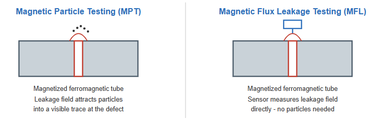
Magnetic particle testing (MPT) applies specifically to ferromagnetic tube - carbon and low-alloy structural steel qualifies, but non-magnetic materials do not. The tube is magnetized, either with a yoke, coil, or direct current passed through the material, which establishes a magnetic field running through the steel. Where a surface or near-surface defect interrupts that field - a crack, a seam, a lack of fusion - the magnetic field lines locally distort and "leak" out of the surface, creating a localized leakage field at exactly the defect location.
Fine magnetic particles (dry powder or a wet suspension) are then applied across the magnetized surface. The leakage field attracts and holds the particles at the defect site, forming a visible line or cluster that traces the shape of the defect - a crack shows up as a particle line following the crack path; a rounded inclusion shows up as a particle cluster.
The appeal of magnetic particle testing is directness and cost: equipment investment is comparatively low, the physical indication is highly reliable where it applies, and the defect is directly visible rather than inferred from an electronic signal - an inspector can see the actual shape and extent of the flaw. The downsides are largely about labor and precision: applying magnetizing current, particles, and interpreting the pattern is a manual process, which raises labor cost relative to an automated in-line method. It also cannot distinguish defect type or severity grade with the same precision as ultrasonic or eddy current testing - it tells you a defect exists and roughly where, but not necessarily its depth or exact classification - and overall throughput tends to be slower than automated alternatives.
| Aspect | Magnetic Particle (MPT) | Magnetic Flux Leakage (MFL) |
| Result readout | Visible particle pattern | Electronic sensor signal |
| Sensitivity / reliability | Good | Higher than MPT |
| Labor / speed | Manual, slower | Automated, faster |
| Applicable range | Narrower | Broader |
| Material requirement | Ferromagnetic only | Ferromagnetic only |
How Does Infrared Induction Thermography Testing Find Defects by Temperature?
Infrared testing on tube surfaces is typically implemented as induction thermography, and the principle is distinct from the other four methods: it detects defects through localized heating rather than a magnetic or acoustic signal. A high-frequency induction coil is passed near the tube surface, generating an induced electrical current directly on the tube's surface layer. Where the material is sound, that induced current flows evenly and dissipates as heat uniformly. Where a defect exists, the local electrical resistance changes, and the defect region consumes more electrical energy as it carries the induced current - producing a measurably higher local temperature.
An infrared camera or sensor reads this temperature pattern across the surface. Because the rate and pattern of heat dissipation relate to how deep the defect sits, the resulting thermal signature can be used to estimate defect depth, not just presence - which is a capability none of the purely surface-indication methods (like magnetic particle testing) provide directly.
The practical limitation is geometric: this method is generally effective only on flat, straight surfaces, where the induction coil can maintain a consistent, uniform distance and coupling with the tube surface across the scan. It is not well suited to uneven or irregular metal surfaces - a corner radius, a rough weld cap, or an uneven scale layer disrupts the induced current distribution and undermines the reliability of the thermal reading. On square and rectangular tube, this generally confines infrared/induction thermography to the flat faces rather than the full section.
How Does Magnetic Flux Leakage Testing Compare to Magnetic Particle Testing?
Magnetic flux leakage testing (MFL) shares its underlying physics with magnetic particle testing almost entirely - both magnetize a ferromagnetic tube and rely on the fact that a defect distorts the magnetic field, producing a localized leakage field at the flaw. The difference is in how that leakage field is read: instead of applying magnetic particles and relying on a visual pattern, MFL uses electronic sensors - typically Hall-effect or coil-based sensors - to detect and measure the leakage field directly, converting it into an electronic signal rather than a visible particle trace.
That shift from a manual, visual readout to a direct electronic measurement is what gives MFL its practical edge: its applicable range, sensitivity, and reliability are all generally stronger than magnetic particle testing. Because the leakage field is measured electronically rather than visually inspected, MFL can be automated and run at production-line speed, and its sensitivity is less dependent on an inspector's ability to interpret a particle pattern correctly under variable lighting or surface conditions. Like magnetic particle testing, it remains limited to ferromagnetic tube - non-magnetic materials cannot be inspected by either method.


